Sub-Pages
Parts list. Link
RepRap G-Code Link
RepRap G-Code Cheatsheet Link
Use Placeholder Variable in the G-Code for the tool change code.
Improve start and end code. Link
General info on firmware used in the Bukobot Controller Link -
The actual firmware used in Bukobot here
The one file to install in AzteegX3 is Marlin.ino
The motherboard used in AzteegX3 is RAMPS 1.3
Change extruder direction by going into configuration.h file. Download the Bukobot firmware here and find the configuration.h file.
Calibration setting in configuration.h file: (About 4/5 of the way down)
// default settings
#define DEFAULT_AXIS_STEPS_PER_UNIT {55.99,55.99,3200,1260} // default steps per unit for Bukobot
This defines number of steps per 1 mm of movement. The first 3 numbers are the X,Y and Z steps/mm. The last is E, or the extruder feed steps/mm. This is what is in my machine. If production parts changes, these settings will change as well.
This is what is given by the settings
page of the Bukobot site for the Bukobot Duo:
X & Y Steps using 15 teeth / 3.18 pitch synchromesh cable 111.98/mm
at 1/32 microstepping
Z Steps for M6 threaded rods: 6400/mm at 1/32 microstepping
Extruder Steps using Tatsu Drive Gear and 13.6:1 ratio stepper motor (Bukobot):
630/mm at 1/8 microstepping
Remember, stepper motor comes in different microstepping configuration. There is 1/8, 1/16 or 1/32. Reverse calculate to find out what is the microstepping of the stepper motor, and do a sanity check on the default setting in the configuration.h file.
The X and Y axis per Bukobot moves at 111.98 step/mm for 1/32 microsteping motor. The default setting in the configuration.h file is 55.99 steps/mm. Configuration.h file number is twice what website gave. Therefore, the stepper motor in the Bukobot Duo is a 1/16 microstepping motor instead of the 1/32 microstepping motor per the information on the website. Assume that the website is out of date. During manufacture, when Deezmaker gets a batch of stepper motor that is different step rate, they will adjust the number in the configuration.h file to compensate.
The Z axis setting is 3200 step/mm in the configuration.h file, and 6400 step/mm per the website for a 1/32 microstepping motor. Is about half in the actual hardware. Therefore, the Z axis stepper motor is a 1/16 microstepping motor also.
For the extruder, hardware value is 1260 step/mm. Website said 631 step/mm for a 1/8 microstepping motor. Hardware is twice the number of steps. Therefore the stepper motor is a 1/16 mircrostepping motor.
Summary: All X,Y,Z and Extruder are 1/16 step microstepping motor. At least for my machine. Expect hardware to change though.
The default axis steps per unit in the configuration.h file is a starting place. Once you measure the actual part made, you can change the numbers to calibrate the Bukobot.
Triffid Calibration Guide Link - More involved calibration
Simple Calibration Guide Using Filiment Setting->Extrusion Multiplier setting Link
Calculation of flow rate. Link
Setting calculator for Makerbot Link
Skineforge flowrate calcuation comments Link
Clear material: The most clear material. Link
MatterHackers - In Orange CA. Lots of 3D printer parts and filament.
Maker Geeks.com - In Missouri
Hobbypartz.com - Has filament and 3D printer parts also.
Filaflex from recreus.com is the worse.
HIP from Lulzbot recommended by whosawhatsis on Bukobot forum.
Borosilicate glass bed from Lulzbot.
Google 3D Printer Forum Link
Cause of Z ribbing. Many reasons why there are steps on the Z axis. Link
Blog on improvement to Ultimaker. Interesting articles about resolution as well as talking about Cura slicer program. Sounds like a very good program. Link
Every type of 3D printer and parts available. Link
Universal Filament project. Purpose is to have a universal filament testing and spec system. Link
Set the perimeter speed to less than 100mm/s for nice exterior finish.
If nozzle is too high from the plate, the first line will be wiggly.
If nozzle is high on the sides, but low in the middle, then plate could be warped, but more likely the rod is bent. Rotate rod and check again.
Extrusion speed can be no more than 1.5-2 mm/s in the Slic3r or 90-120mm/min in the Repetier. Note they use different units. Slic3r is mm/s, and Repetier and G-Code output is mm/min. Multiple or divide by 60 to go from one to the other. That can mess you up.
If extrusion speed is faster than 2mm/s, the safety clutch in the extruder will start to skip, and it won't extrude until the next detent is reached. You may not hear the clicking, but you will end up with parts of the model that has no material on it. You may think you need to extrude more material. However, the solution is to make sure the extrusion speed is low enough. One area you are most likely to run into this problem is setting the retract speed in Slic3r. The default retract speed is 21mm/s. Way too fast for extrude, but ok for retract. Therefore, if you retract say 1mm, and the material you are using like to ozze out and fill the nozzle, then when it comes time to extrude again, the nozzle is already filled by the ozzing out of material. Then when extruder tried to extrude again at 21mm/s, is going too fast, and the clutch releases. You end up with missing material on the part.
ABS parts like to warp. Problem is as first layer cools, it shrinks. Subsequent layers are laid on top of the cool shrunk first layer. As the subsequent layers cools, it warps the part. Solution: For the first run of the day, heat the plate up to 120C instead of 110C. This will keep the parts warmer. Put an air deflector in front of the machine so the part stays warm longer. Also build a wall around the part. That will act like a thermal insulation to keep the part warm. At about 150C for ABS, the plastic can stretch. If the base plate is set to 120C, then the temperature difference would be only 30C. That would not cause too much bending of the part. After the machine has fully warmed up, the plate can be lowered to 110C because the heat all around the machine will keep the part warm. Remember, this is in Los Angeles. If you are in cold climate, you will need warmer settings.
1. Pull tape slowly. Fasten edge of tape to edge of table and unroll tape slowly and evenly. If too much force is applied, the edge will stretch, and cause wrinkle. This is where it helps to have a wide 3" tape.
2. Use a drafter triagle and put tape on the triagle so only about 1/4" is extending beyond the triangle. The triangle is rigid, and will hold the tape when positioning. More importantly, it will keep the tape straight while positioning.
3. Position the tape with the 1/4" extended edge. When edge adheres, pull off the triangle and apply the rest of the tape. Make sure the tape is smooth and rub in one side at a time.
4. Peel off and reapply if there are large bubbles.
5. Heat and cycle the tape once or twice, remaining bubbles will disappear.
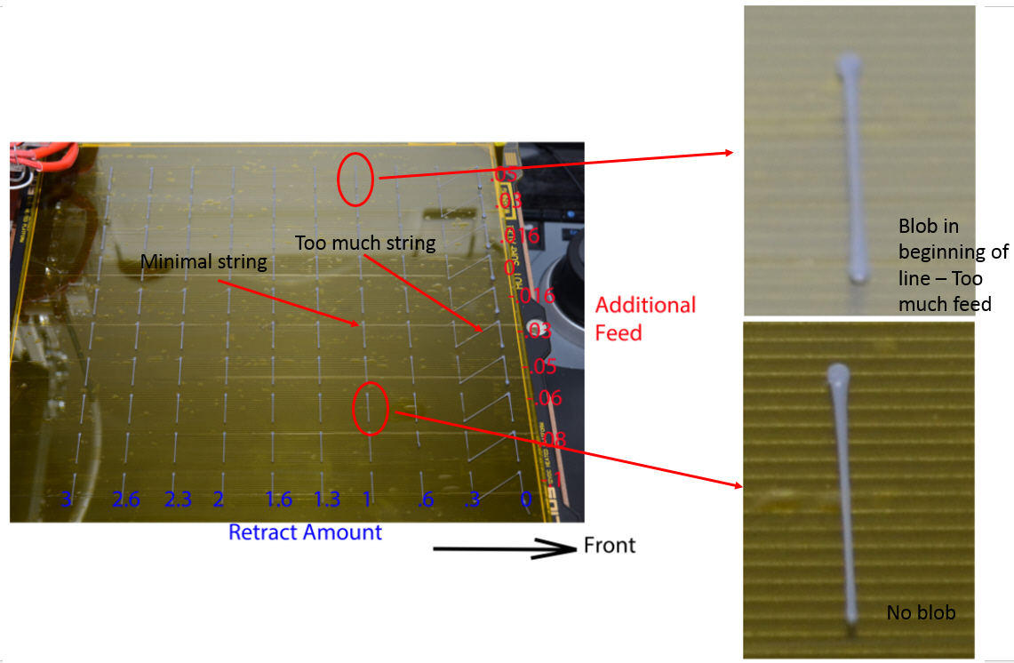
Use this spreadsheet to generate G-Code that will lay down 100 lines with different retract and additional feed. Find out what setting works best quickly.