The stock Walkera ESC is relatively heavy at 3.2grams. On the other hand, the TGY DP 3A from Hobby King or Ebay weighs only 1 gram. Is tempting to use a lighter and cheaper ESC for better performance. However, the FETs on the original ESC is very low quality. (How else do they keep the price so low) They have a lot of resistance, and will get hot during flight. This modification replace those low quality FETs with the best available to transform the low quality ESC into a high performance ESC.
1. Brushless ESC. Get the TGY DP 3A. Also know as the Aeolian 3A ESC$11.40. Can also use a similar HobbyKing XP 3A 1S. (The XP 3A 1S use to not work very well if at all with outrunners, but now with BLHeli that resolved the original program. BLHeli erase the original program, and put in the opensource program. Now both the DP 3A and XP 3A have the same program, and works equally as well.).
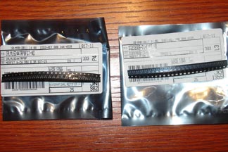
2. Get the following FETs. They work for both the DP 3A and the XP 3A.
IRLML6244TRPBFCT-ND 6.3Amp MOSFET N-Channel from Digikey $.51 each. 3 needed.
SI2333DS-T1-E3CT-ND 4.1Amp MOSFET P-Channel from Digikey $.91 each. 3 needed.
Total cost is about $15, and you get a super light ESC.
The TGY ESC is great, is small and light, but does have some weak FETs. FET is short for MOSFET. It is what turns power on and off in the ESC. The TGY 3A ESC can handle the power requirement of the 4#3A helicopter. However, the ESC does get hot after a while. You could feel the back of the circuit board getting quite hot after a flight. The FETs on the other side must be even hotter. ( The FETs were against the receiver, so can't touch them) Heat means the battery is used to heat up the FET instead of powering the motor. Is robbing the motor of power. Of course, if it gets too hot, it will burn up the FET. The FETs that came with the TGY 3A ESC were probably generic SOT-23 FETs. It was probably sourced base on price alone. If you swap them out with some quality Vishay or International Rectifier units, you can lower the on resistance of the FET. Lower resistance means faster motor and longer run time. Also means it can carry more current without overheating. Lets get to work.
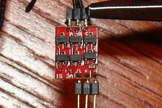
These are the original generic FET. Get hot with current.
First step is to use a soldering iron to remove the FETs. FETs are spaced quite wide apart from each other, so is not too hard with a fine tip soldering iron.
FET removal tip: Fet has 2 legs on one side and 1 leg on opposite side. If you heat one side up, it will cool before you get to the other side. All solder must melt at same time for the chip to come off. Solution: Put a blob of solder on the 1 leg. The blob of solder acts like a heat resevoir and keep that leg hot. That gives you enough time to heat the 2 legs on other side up at the same time. (Assume the solder tip is wide enough) The chip will slide right off.
Next, get the new quality FETs.
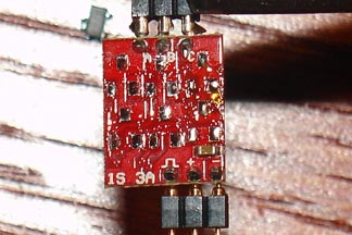
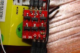
Solder the quality FETs on. Note, the P-channel FETs (item #9 in parts list) go on the bottom and N-channel FET (item #8 in parts list) go on the top in the pictures above and below.
Soldering tip: If it ain't smoking, you ain't soldering.
Solder has flux on it. The flux burn off as smoke on the soldering iron. When all the flux burns off, smoke stops. Therefore, clean the tip with sponge etc, then put some fresh solder on the tip. While the tip is smoking, solder the joint. For these FETs, the solder left over on the board and on the tip of the iron should be enough to make the joint. No need to add more solder. Use a tweezer to hold the FET while you solder one leg. Then go on to the next and the last. Once one leg is soldered, don't touch the FET with the tweezer anymore. Is stuck already, and you will break the circuit board if you move the FET with one leg soldered. Just heat the second joint to get that soldered and the last. Use magnifying glass to make sure all the legs have a nice solder joint. If one of the joint looks questionable, this is where a flux pen comes in handy. Add flux to the joint and reheat. Flux on the joint will make a nice shinny joint. Flux also increase surface tension on the solder so it stick to both contacts and make a solid connection.
Testing with 320mah Hyperion cells.
Run time was about 5:20 for my other Chinese Jade brushless conversion 4#3A that weight about the same as stock.
Run time increased by a minute to 6:25 with stock TGY 3A ESC and brushless motor along with light weight linear servo. Not bad, but FETs get hot.
Run time increased by about another 40 seconds to 7:05 with the new FETs. The ESC barely got warm! That is quite an improvement with new FETs.
That is over 7 minute run time on a 320mah cell. Quite good.
The 3A ESC in stock form can hardly handle enough power to fly the 4#3A helicopter. However, with the modified FET, it flys the helicopter without even heating up the FETs. Question is how much more can the ESC handle. Base on testing by Microchip in their paper AN792, the SOT23 package has a thermal resistance of 130C/Watt to 260C/Watt depending on circuit board configuration. Assume you stack the FETs 3X. See AtomicMods for stacking FETs. the collective resistance will be .0116 ohms. Assume the maximum allowable temperature for the FET is 100 F / 37.8 C. Use average thermal resistance of 195 C/W. At 37.8 C, heat dissipation of the FET will be .194 Watts. Each FET can then handle sqrt(.44/.0116) = 4.08 Amps. Now, since this is a 3 phase motor, that means each FET turns on only 1/3 of the time. That is 33% duty cycle. Therefore, with 3X stacked FETs, the ESC can handle is 12.3 Amps! With only 1 layer of modified FET no stacking, the ESC can handle 7 Amps. Not bad for just changing the FETs on the ESC.